Zasady zabudowy i obsługi manipulatora PS12 i SSP/en: Różnice pomiędzy wersjami
(Utworzono nową stronę "For case presented on pic. 5. there is single track (track no. 1). In even direction we have level crossing distant signal called "118". In opposite direction for operat...") |
(Utworzono nową stronę "== Building the crossings with sensors ''Remote_axle_counter'' == When a crossing is placed near to the border of scenery or the necessary distance of sensors is bigger...") |
||
| (Nie pokazano 2 wersji utworzonych przez 2 użytkowników) | |||
| Linia 39: | Linia 39: | ||
<br> | <br> | ||
| + | |||
| + | == Building the crossings with sensors ''Remote_axle_counter'' == | ||
| + | When a crossing is placed near to the border of scenery or the necessary distance of sensors is bigger than the available distance on the scenery, we use ''Remote_axle_counter'' sensors. They're called in the same way as the normal sensors (like shown on the picture no. 6 on this page). The only difference is "AC Distance" window which is filled with the difference between the necessary (according to regulations) distance and the real distance of sensor on the scenery. For instance, a sensor has to be placed 1647 meters far from the crossing but we have only 1015 meters of track available on the scenery (only to the border with a magic forest). We place a sensor directly next to the magic forest, call it properly and then we fill ''AC Distance'' with the difference between real and according to regulations distance, as in our case this difference is 632 meters. | ||
| | ||
Aktualna wersja na dzień 11:26, 30 cze 2024
Spis treści
- 1 PS12 manipulator building and usage
- 2 Single barrier railroad crossing operating (only right barrier at two sides)
- 3 Operating double barrier crossing (left and right barier at two sides)
- 4 Rules for building the automatic railroad signalling for centralised mechanical-powered signalling equipment
- 5 Repeater manual
- 6 Building the crossings with sensors Remote_axle_counter
PS12 manipulator building and usage
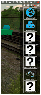
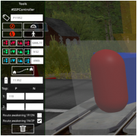
PS12_04_v01 manipulator is used to manage cat-A (manual) railroad crossing barriers and signalling. Manipulator is available in editor menu like in picture 1. Manipulator should be placed in the signal box, in label textfield (picture 2) enter crossing ID. This ID is also assigned to barriers (Picture 3) and signalling (Picture 4). RgP suffix should be used with rigght barrier (RgL - left barrier) and SD for signalling.
Single barrier railroad crossing operating (only right barrier at two sides)
To open the crossing hold left green button until green led will lit up. Do similar for closure - hold left red button until red led will lit up. Clicking button while left ALT key is pressed will close/open the crossing without holding button of the manipulator (or will continue opening/closure).
Operating double barrier crossing (left and right barier at two sides)
To operate this kind of the level crossing use left green/red button while left SHIFT on your keyboard is pressed.
Rules for building the automatic railroad signalling for centralised mechanical-powered signalling equipment
To make a new properly working automatic railroad crossing (cat. B or C):
1. Insert #SSPController object on the crossing or near to them (you can find it in this same place like PS12 manipulator (Picture 1)).
2. Enter RR-crossing ID to the controller (Picture 5).
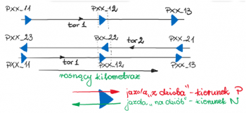
In the textfield marked by milestone symbol input kilometer of your crossing (will be displayed on the repeater in the signal box). In P and N fields type identificators of crossing distant signals on tracks 1 and 2 for desired driving direction (P, N) on the track (direction is predicted by method of placing detectors on track (see Picture 6 - currently in Polish language).
For case presented on pic. 5. there is single track (track no. 1). In even direction we have level crossing distant signal called "118". In opposite direction for operations on track no. 1. there is no distant signal and activating crossing is emerged by giving permitting signal for desired track (in case of reserving track by train before allowing exit signal). This same function is operated on crossings addicted to routes set by SCS, SPE and SPK.
3. Sensors (blue arrows) are placed in true distance from crossing (two pass-thru detectors) and disabling sensor on the crossing. Rules of detectors enumeration and drivind direction (P - even; N - opposite) are detailed here (pic. 6.). 4. Place repeaters in signal box (ERP-5 for older crossings without distant signals or ERP-6 for newer one)
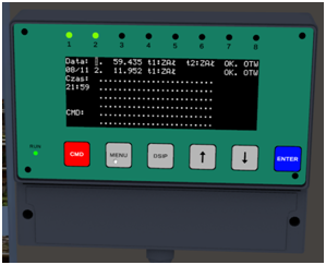
- ERP-6 can display status of up to eight crossings (Pic. 7.). In this case repeater is controlling two crossings (identified as P59435 i P11952)
- ERP-5 (Pic. 8.) we can insert data of only one crossing (in this case it is identified as P56064).
5. Optional crossing addiction in train routes. In this case, you have to select "Route Awakening" checkbox in desired crossing controller. For P11952 crossing (pic. 5.) driving on single track is proceeded with addiction on exit routes (in opposite direction is referencing to blue detectors setup). Select checkbox labeled 1N. 6. For crossing on double track (Pic. 9.) driving to track 1. is proceeded in even direction and to track 2. in opposite direction. So you must select checkbox 1P/2N. Be aware of driving direction for the detector while crossing devices awakening.
Repeater manual
Correctness of all entries in ERP-6 repeater is alerted by proper amount of leds on hed panel of the device. In this case, two crossings (Pic. 10.). Executing of commands is performed by choosing desired crossing by up/down arrows and pressing CMD button to select correct command (Reset, T1wył (first detector off), T1zał (first detector on), T2 wył (second detector off), T2zał (second detector on)). After selecting proper command press ENTER and confirm are you sure by pressing CMD again. After pressing MENU button on the front panel you can display information about state of all controlled crossings (Rys. 11). Actiual time and date, kilometer of every crossing, power state of all detectors (t1:ZAŁ, t2:ZAŁ for double track or only t1:ZAŁ for single one), status of crossing closure (OK. OTW (opened) lub OK. ZAM (closed)) are shown. Enabling warning for desired crossing is alerted by blinking proper led on head panel.
In case of ERP-5 repeater it's possible only to send crossing reset signal, centering cursor on main panel and pressing "E" key on keyboard (Pic. 12). Activation of crossing warning devices is marked by blinking green led (other lights should light without blinking) and hearable ticking of the relay.
Building the crossings with sensors Remote_axle_counter
When a crossing is placed near to the border of scenery or the necessary distance of sensors is bigger than the available distance on the scenery, we use Remote_axle_counter sensors. They're called in the same way as the normal sensors (like shown on the picture no. 6 on this page). The only difference is "AC Distance" window which is filled with the difference between the necessary (according to regulations) distance and the real distance of sensor on the scenery. For instance, a sensor has to be placed 1647 meters far from the crossing but we have only 1015 meters of track available on the scenery (only to the border with a magic forest). We place a sensor directly next to the magic forest, call it properly and then we fill AC Distance with the difference between real and according to regulations distance, as in our case this difference is 632 meters.


