BuilderHelpEn
Spis treści
Quick Notes
The Editor is still in the process of implementation and refinement. There will be bugs, there will be odd behaviours, and there may be missing features. If you encounter any of those, please post on the Forums and we�ll see what we can do. Because the Editor is still being worked on, things can change with no warning. We�ll try to make major changes as painless as possible.
Controls
The Basics
[#top Back to Top]
Camera Controls
In the editor there are three camera modes:
All three camera modes use the same controls, but the behaviour is slightly different. Additionally,there is a slider at the bottom right of the screen which you can use to control your camera speed.
[#top Back to Top]
Additional Keyboard Shortcuts
[#top Back to Top]
Tools
General Tools
[#top Back to Top]
Object Tools
[#top Back to Top]
Laying Tracks
Getting Started
In Train Driver 2 the main way you place tracks is with connection points. There are two different connection points: standard connection points and route connection points.
[#top Back to Top]
Standard Connectors
These connectors are used for placing all the tracks around your station. When you place them in the station, they are simply a point with a direction. The arrow indicates which direction child track pieces will go in. To place tracks, select �Place� and select what kind of track you�d like to place.
Track Piece Types
It�s pretty straightforward what all these types (and sub-types), but take some time to familiarise yourself with the options.
[#top Back to Top]
Auto Tracks
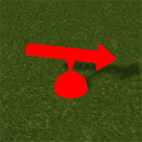
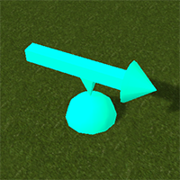
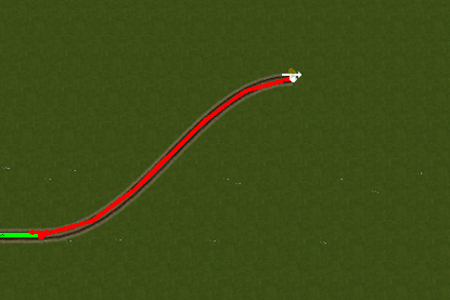
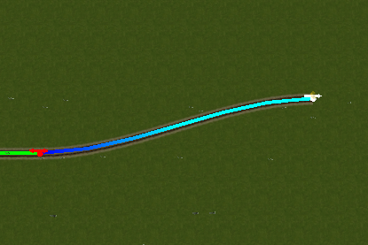
Auto tracks are one of the most commonly used tools in the editor. They are also one of the most programmatically complex tools, and is rather experimental. Selecting auto tracks on a node will generate a new standard connector node, which is in free movement mode. You can move this new node wherever you like and the indicator will be red when the track is not valid, and will change to blue when it is. You can also connect two segments of track using this tool.
[#top Back to Top]
Route Connectors
These connectors are used to place the entry and exit points to your station. Make sure they are connected to the rest of your tracks before you go to Dispatcher Mode, otherwise someone might crash. Route connectors behave a bit differently from standard connectors.
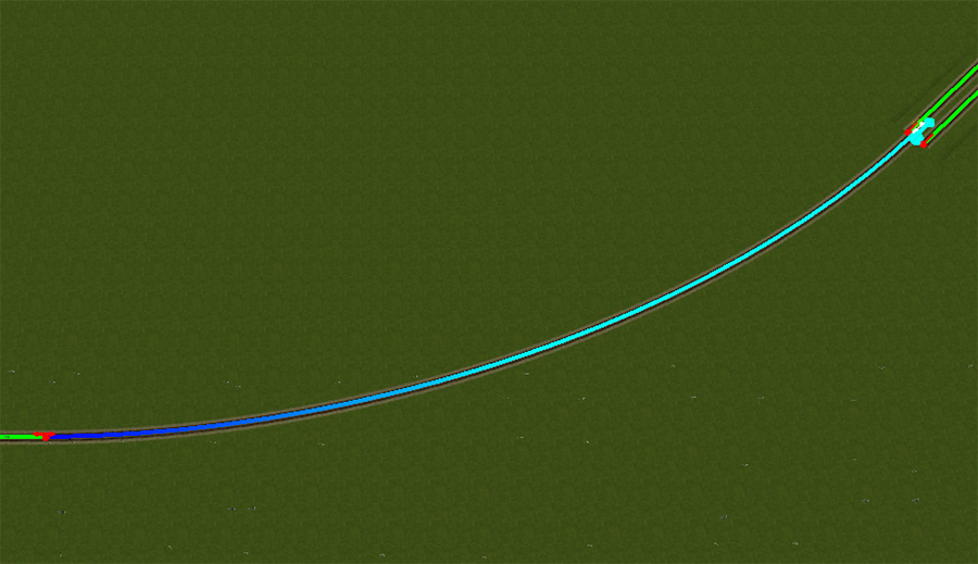
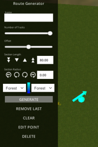
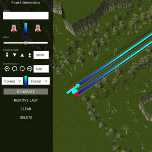
For starters, they can generate additional scenery (currently only forest), which can�t be edited. They don�t count as standard connectors, and you must generate at least one segment in order to be able to connect the route to the rest of your station. To select the internal standard connectors, simply click on the buttons which appear under the name when you generate the first segment.
Inside the Route node, you can find options for generating the route scenery, including the number of tracks (currently max. 2), their offset and whether the route is plain or forested. If you need to change the position and orientation of the node, it must have no generated scenery. You can remove the last generated segment of the route by clicking �Remove Last�.
Connect the Route to the rest of your station
[#top Back to Top]
Advanced Tools
Still being implemented :)
[#top Back to Top]
Wrangling the Catenary
Getting Started
The catenary is what powers your electric trains (like the EU07). You can find the Catenary objects here:
There are three sub categories within Catenary
an icon for catenary signs Catenary signs
an icon for misc catenary objects Misc Catenary objects
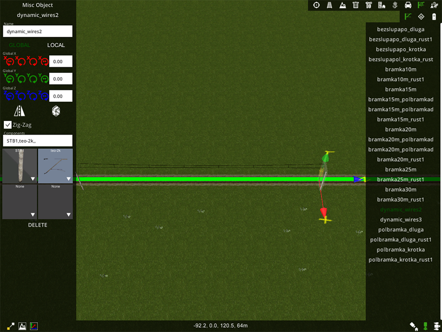
The objects you�ll be using the most are dynamic_wires2, as these will generate wires as you place the posts. Typically the wires zig-zag, but you have the option to disable them (e.g. for curved tracks). Signs and misc catenary objects will snap to the posts as long as snapping is enabled.
[#top Back to Top]
Catenary Conventions
There are some basic rules which you should follow in order to build awesome, realistic stations:
- Catenary posts should be approximately 70m apart. On curves, they should be more bunched so that the wires are always over the tracks.
- The ruler at the bottom of the screen will tell you how far from the selected object the mouse cursor is
- The catenary wires should not zig-zag on curves
- The exact formula for how far apart they should be on curves is:
lengthOfCatenarySegment = 2 * sqrt(offset * (2radius+offset));
Below is an example of some curve radii and how far apart the catenary posts should be in that case:
| Radius (m) | 150 | 180 | 200 | 250 | 300 | 350 | 400 | 500 | 600 | 700 | 800 | 1000 | 1200 | 1500 | 1800 | 2000 |
| Distance (m) | 22 | 24 | 25 | 28 | 31 | 33 | 36 | 40 | 44 | 47 | 51 | 57 | 61 | 69 | 75 | 80 |
The catenary signs are used in specific places, and are placed as following:
| Sign | Position | Meaning |
| We1 | 500m before We2 | Slow to 60 km/h and prepare to lower pantographs |
| We2 | 100m before the driver should lower their pantographs | Lower your pantographs |
| We3 | 200m after the point drivers can raise their pantographs safely | Raise your pantographs |
| We4 | Before the end of an electrified line | No entry for electric locomotives |
| We8 | 30m before the beginning of a catenary block | Draw no power |
| We9 | 200m after the point where drivers can safely begin drawing power again | Safe to resume drawing power |
[#top Back to Top]
Decorating your Station
Placing and Moving Objects
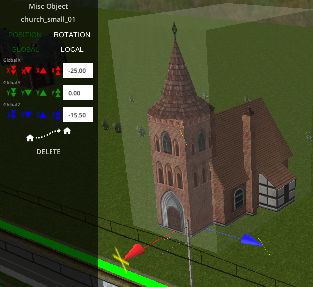
Simply select the object you wish to place, then click on the map where you want it. You can move objects around using the object panel on the left side of the screen. Rotation works the same way, but you can�t move an object and rotate it at the same time. You can also use the free movement tool. The object will stay on the ground and follow the cursor position.
[#top Back to Top]
Object Types
Standard Objects
Standard objects are pretty much like most objects in most editors. They have a single model, which you can move around, and that�s about it.
[#top Back to Top]
Compound Objects
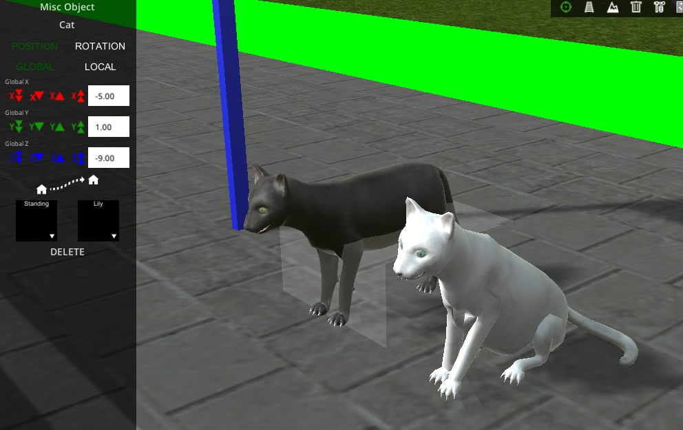
Compound objects are like standard objects, but they have additional options available that standard ones don�t. For example, a digger might have only one model or texture, a cat might have different textures available, or the rail crossing sign, might have additional arms or bells.
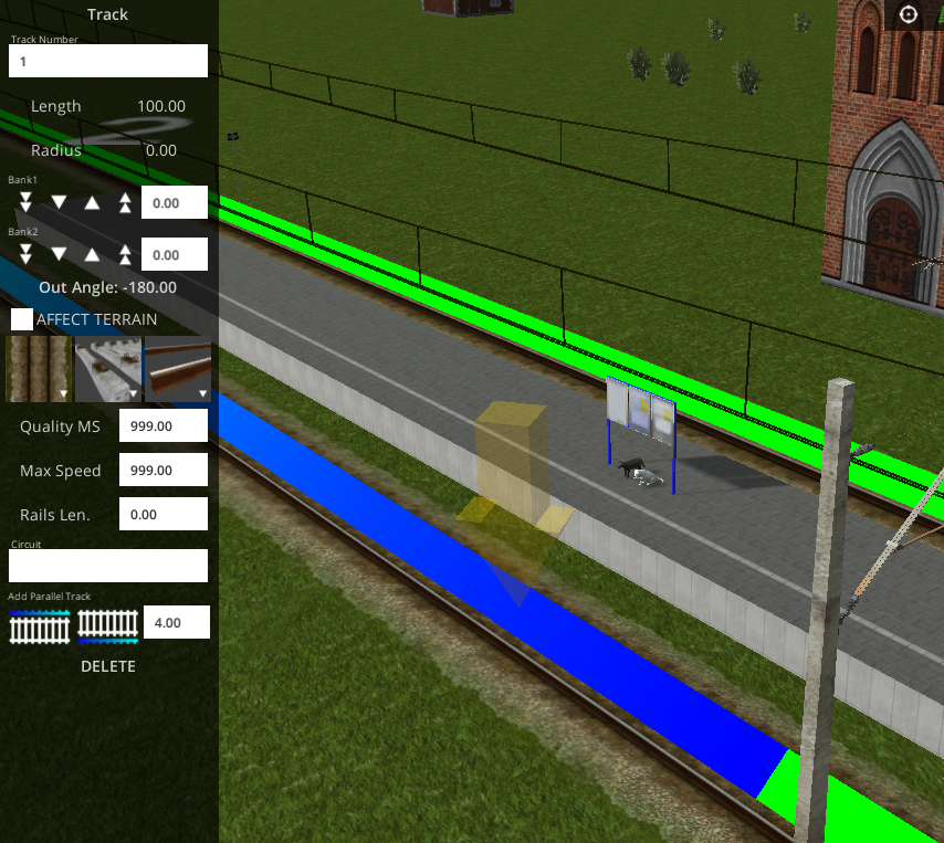
The first compound object you are likely to come across are the tracks themselves, where you can change the ballast, sleeper type and rail texture.
[#top Back to Top]
Sculpting the Terrain
Terrain Editing in TD2 is the most eclectic part of the editor, and is still subject to change. The terrain is handled using TerrainPoints, which you can place and move around to raise or lower parts of the landscape. TerrainPoint are found in the Terrain tab.
There are three main types of TerrainPoints in Train Driver 2:
Red TerrainPoints Automatically generated by objects when you select the Affect Terrain checkbox. These ones cannot be generated any other way, and will update when you move the object they are attached to.
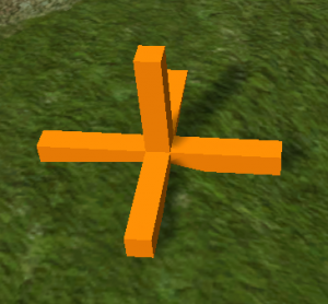
Orange TerrainPoints These are the main points in the Terrain tab. You move and place them like standard objects.
Purple TerrainPoints These are special terrain points which are used in groups.
[#top Back to Top]
Terrain Groups
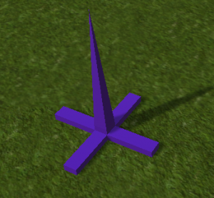
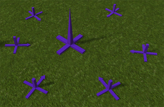
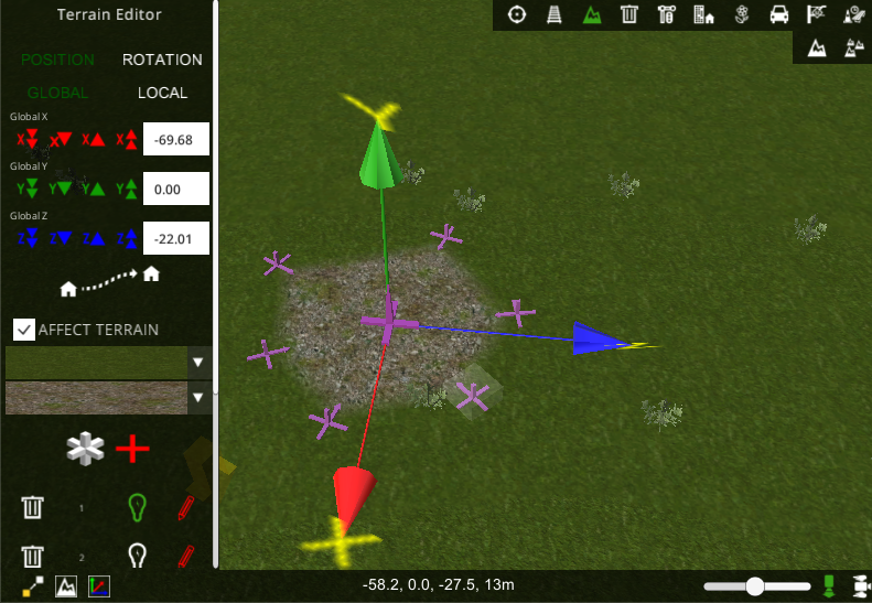
You can edit whole groups of TerrainPoints at once using Terrain groups. To create a group, you need to place one of the purple TerrainPoints. This TerrainPoint is larger than the others and has a spike on top. This is the central point of your group. Moving this point will move all the points in the group at once. You can spawn the smaller points from the central one. These can be moved individually by clicking on the pencil icon next to the selected object in the group�s object list.
The smaller purple TerrainPoints have an arrow which initially points toward the central one. This arrow indicates the �inside� of the group. This is useful for changing the texture of the groups. The top box is the outside of the group, and the lower one is the inside.
There are other kinds of TerrainPoint groups coming, watch this space!
Thanks for reading this manual, I hope this helps!
[#top Back to Top]

