RASP-UZK instruction
Spis treści
About the program
The Simulator of Crossing Devices (SUP) is the simulator of remote control devices RASP-UZK in versions 4F 2.0 and 4.4Ft. In the simulator SUP also works as crossing container, being responsible for reporting its state to UZK and following the orders.
SUP doesn't support at the moment the crossings which are confirmed in rail courses, also aroused by rail courses and on many-track routes (by >2 tracks RASP serves as the additional signalisation on the crossings of A category). It's also supported to double sensors by adding a letter 'a' or 'b' at the sensor's end.
Hardware requirements
► The recommended operation system Microsoft Windows 10 64-bit or newer (on version Windows 7 64-bit Service Pack 1 turns on but its operation isn't guaranted)
► .NET Framework 4.8
► >10MB free space on your hard drive
► Monitor with minimal resolution 1024x768
Making the connection with the scenery
After starting up the scenery in dispatcher mode, you must load a configuration file by selecting in the menu Plik > Wczytaj.
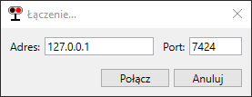
After that, you should start the connection by selecting Plik > Połącz. In the new window you must confirm host's IP adress and port number, otherwise you should correct those datas.
The process of connection lasts about 20 seconds. In this time railroad crossings are set to the default state, then during a train ride YOU MUST NOT start a new connection with the simulator.
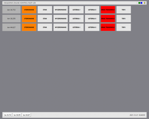
The main window (4F 2.0)
In the main window there is shown basic information about monitored crossings. Reproduction of SSP state is realised with filling the apropriate fields with colours. Defects are signalised additionally with a continuous sound (I category) or interrupted (II category).
► Fields in main window
| Field name | Field colour | |
|---|---|---|
| (crossing's name) | » crossing's kilometer | |
| STEROWANIE | » greeen - steered automatically » orange - local steering | |
| USTERKA I | » gray - no defects of I category » red blinking - defect of I category | |
| USTERKA II | » gray - no defects of II category » red permanent - defect of II category | |
| TRANSMISJA | » gray (TRANSMISJA OK) - transmission correct » red (BRAK TRANSMISJI) - no connection with the simulator or batteries are dead | |
| TOR I | » gray - sensors on the no. 1 track are enabled » red- sensors on the no. 1 track are disabled | |
| TOR II | » gray - sensors on the no. 2 track are enabled » gray - sensors on the no. 2 track are disabled | |
The main window (4.4Ft)
Like in 4F 2.0 UI, the main window in 4.4Ft presents basic information about controlled crossings and status of proper crossings is displayed as filling fields with information about it. Failures are also marked by the sound signal: still (cat. I) or broken (cat. II).
► Fields in the main window
| Field name | Field colour | |
|---|---|---|
| (crossing's name) | » crossing's kilometer | |
| STAN (simplified crossing's scheme) |
» white - no SUP communication with TD2 » purple - awaiting » gray - warning » red/white blinking - defect of I or II category | |
| STEROWANIE | » green (OK auto) - automatical steering » orange (OK lokalnie) - local steering | |
| ZEROWANIE | » gray (OK zer.) - default state » darkred (Zerowanie) - remote opening | |
| USTERKA I | » gray (OK ust. 2) - no defects of I category » red blinking (Ust. kat.1) - defect of I category | |
| USTERKA II | » gray (OK ust.2) - no defects of II category » yellow (Ust. kat.2) - defect of II category | |
| TRANSMISJA | » gray (OK transm.) - transmission correct » red (BRAK transm.) - no communication between SUP and TD2 or batteries are dead | |
| ZASILANIE | » gray (OK 230V) - SSP container sourced from the main » orange (BRAK zasil.) - SSP container sourced from the battery | |
| TOR I | » gray (Tor 1 ZAŁ.) - sensores of track 1 on » red (Tor 1 WYŁ.) - sensores of track 1 off | |
| TOR II | » gray (Tor 2 ZAŁ.) - sensores of track 2 on » red (Tor 2 WYŁ.) - sensores of track 1 off | |
Detailed window (4F 2.0 & 4.4Ft)
View of detailed window 4F 2.0
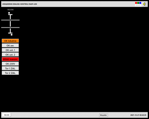
View of detailed window 4.4Ft
Entrance to the particular window can be done by choosing the right crossing on the bar at the bottom. Except small visual differences it's the same in 4F 2.0 and 4.4Ft. In the window there is shown particular information about the crossing's state and the list of statements got from the system. The particular window allows to send the order by choosing the right button with Ctrl keypad and right mouse button.
On the upper bar there are 7 fields (5 for C crossing's category). Filling that field with red color means that there has appeared a fault of the I category.
► Crossing's scheme
In the central part there's a crossing's scheme. The scheme shows the mapping of tools on the crossing. Zone filling means the occupying by a train. The interpretation of train's movement direction takes place by occupying the following zone.
► Functional buttons
On the left side of the particular window there are functional buttons (table).
| Field name | Field colour |
|---|---|
| Zezwolenie na ster. LOKALNE (4F 2.0) Sterowanie LOKALNE (4.4Ft) |
» orange - crossing is manipulated locally (manually) » blinking orange - allowed for local manipulation » gray - steered automatically |
| Sterowanie AUTOMATYCZNE (4F 2.0) Sterowanie AUTOMAT. (4.4Ft) |
» green - crossing is steered automatically » blinking green - crossing is steered locally (only 4.4Ft) » grey - local steering |
| T1 ZAŁ. / T2 ZAŁ. | » gray - sensors in the track off » green - sensors in the track on |
| T1 WYŁ. / T2 WYŁ. | » grey - sensors in the track on » red - sensors in the track off |
| ZEROWANIE | » gray - default state » purple (4F 2.0) - system zeroed via the remote control system » darkred (4.4Ft) - system zeroed via the remote control system |
Blue filled blinking field means that the order has been given out but not sent. To send the order Enter keypad must be used. The time for sending the order with Enter pad is timely limited up to 20 sec for 4F and up to 9 sec for 4.4Ft. After order sending the field changes color into.
► The way of using function buttons
Circumstances were shown in Fault table.
The order choosing takes place every time by clicking on the right field with right mouse button with a keypad Ctrl (Ctrl+RMB). After choosing the command, you must transmit it by pressing Enter.
In case of fields T1 zał / T2 zał and ZEROWANIE before choosing the order additionally there will be shown a window UWAGA. The time to click a the button Dalej is time-limited.
In case when the field's color is another than the default state or SUP isn't connected with TD2 it's impossible to choose the order.
► Turning on and off the track sensors
Turning off / on the sensors is used by track repairs, a ride of measure train, a defect of turning on sensor.
Field T1 ZAŁ. / T2 ZAŁ. in green means that sensors are on. T1 WYŁ. / T2 WYŁ. in red means that sensors are off.
WARNING: after turning off the sensors signalisation won't be turned on by the train ride! If there are no TOP signals, the speed must be reduced to 20 km/h with a proper written order (Rozkaz pisemny)!
► Setting the crossing to default state
Setting the crossing to the default state is an attempt to set everything to the default state - turning off the warning. It should be done after fault's appearing. After setting to the default state there's done whole crossing's diagnostics while which the faults can be found again.
The ride of the first train on any track and in any direction should be completed with reduced speed (for crossings with TOP there'll be litten orange lights).
If the fault doesn't pass after setting to the default state, you'll have to follow orders written in Fault table.
► Automatic / local steering
In SUP there's no possibility to change the local steering way to automatic and in opposite way. SUP changes work mode automatically after connecting with the simulator and after setting the crossings to default state.
Alerts
Down in the detailed window there's a list of statements which appeal to the SSP crossing.
Information included in announcements:
► state of crossing devices,
► crossing state,
► appearing the faults on the crossing,
► faults' confirmation.
By using the right mouse button there'll be shown a context menu which allows to change the mode of displayed statements (simplified or detailed list).
Settings
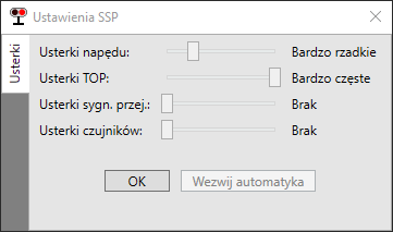
After choosing in the menu Narzędzia > Ustawienia there opens a settings' window. The settings are global - it means that they appeal to all SUP instances irrespective of loaded configuration crossing's file.
Zmiana częstotliwości występowania konkretnej usterki losowej odbywa się poprzez przesunięcie suwaka w żądane położenie.
| Level | Multiplier |
|---|---|
| None | 0 |
| Very rare | 0,5 |
| Rare | 1 |
| Frequent | 2 |
| Very frequent | 5 |
Button Wezwij automatyka służy do usunięcia usterek. Po jego użyciu należy postępować w sposób wskazany przez automatyka.
Editor
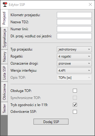
SUP pozwala na samodzielne tworzenie plików konfiguracyjnych przejazdu za pomocą wbudowanego narzędzia.
► Crossing
| Field | Value |
|---|---|
| Crossing's kilometer | form XX.YYY |
| TD2 name | form PXXYYY |
| Line number | text |
| The crossing's length along the road axis | digit from range 6-50 |
| Crossing type | one-track / two-track |
| Barriers | 4 barriers / 2 barriers / no barriers |
| Road designation | vertical / sloping / none |
| Interface version | 4.4Ft / 4F 2.0 |
| TOP description | TOPx [xx] / TOPx xx / TOPx |
| TOP usage | no / yes |
| Synchronical TOP (4F 2.0) | no / yes |
| Station names (4.4Ft) | no / yes |
| Tryb zgodności z Ie-119 (4.4Ft) | yes / no |
| Odwrócenie SSP | no / yes |
► Signalistaion
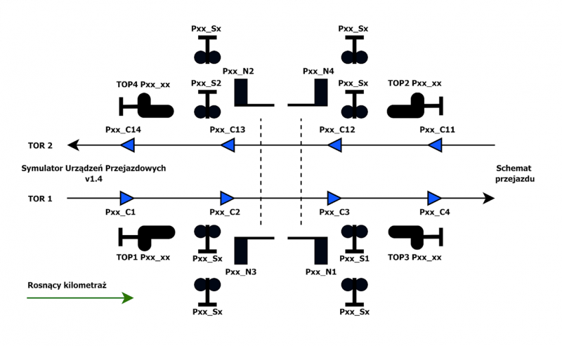
Wybór umiejscowienia od 2 do 8 sygnalizatorów drogowych. Numeracja jest narzucona przez Edytor - na scenerii sygnalizatory drogowe należy nazywać w sposób zaprezentowany w niniejszej zakładce, z dodaniem prefiksu Nazwa TD2.
► Names
Zdefiniowanie nazw tarcz ostrzegawczych przejazdowych (w edytorze bez prefiksu - stosuje się go tylko na scenerii) oraz nazw torów i sąsiadujących posterunków.
► SSP list
Manipulowanie już zdefiniowanymi przejazdami kolejowymi - zmienianie kolejności, wczytywanie, zapisywanie zmian, usuwanie. Dodawanie nowego przejazdu odbywa się w zakładce Przejazd.
► Calculations
Określanie minimalnej odległości czujników włączających od przejazdu z uwzględnieniem:
» minimalnego czasu ostrzegania dla wybranej kategorii,
» czasu zjazdu zestawu z przejazdu,
» sekwencji ostrzegania (8-16-16-6 dla starych wytycznych, 13-10-x-10-7 dla nowych gdzie x - minimalny czas zjazdu zestawu).
Reakcja systemu na sytuację ruchową
► Typical situation
Najechanie taboru na czujnik włączający (C1, C4, C11, C14) powoduje zainicjowanie pracy urządzeń przejazdowych.
- Cykl pracy SSP w trybie zgodności z Ie-119
1) wyświetlanie w ciągu 0,5s sygnału Osp2 na tarczy ostrzegawczej przejazdowej właściwej dla toru i kierunku jazdy,
2) załączenie sygnalizatorów drogowych,
3) po 13s: rozpoczęcie zamykania rogatek wjazdowych,
4) po czasie potrzebnym na zjazd zestawu (obliczany z długości przejazdu, zwykle około 12-15s): rozpoczęcie zamykania rogatek zjazdowych,
5) po zamknięciu: oczekiwanie na tabor przez co najmniej 7 sekund,
6) po zwolnieniu strefy przejazdu (strefa C2C3): wygaszenie sygnału na TOP,
7) po 6s: rozpoczęcie otwierania rogatek zjazdowych,
8) po otwarciu: rozpoczęcie otwierania rogatek wjazdowych,
9) po otwarciu: wyłączenie sygnalizatorów drogowych.
- Cykl pracy SSP w trybie "klasycznym"
1) wyświetlanie w ciągu 0,5s sygnału Osp2 na tarczy ostrzegawczej przejazdowej właściwej dla toru i kierunku jazdy LUB na wszystkich tarczach (tryb synchroniczny),
2) załączenie sygnalizatorów drogowych,
3) po 8s: rozpoczęcie zamykania rogatek wjazdowych,
4) po 16s: rozpoczęcie zamykania rogatek zjazdowych,
5) po zamknięciu: oczekiwanie na tabor przez co najmniej 6 sekund,
6) po zwolnieniu strefy przejazdu (strefa C2C3): wygaszenie sygnału na TOP,
7) po 6s: rozpoczęcie otwierania rogatek zjazdowych,
8) po otwarciu: rozpoczęcie otwierania rogatek wjazdowych,
9) po otwarciu: wyłączenie sygnalizatorów drogowych.
► Untypical situation
W przypadku wystąpienia usterki kategorii I konieczne jest ograniczenie prędkości na przejeździe do 20 km/h. Ograniczenie następuje poprzez wyświetlanie sygnału Osp1 na tarczy ostrzegawczej przejazdowej (selektywnie dla toru i kierunku lub na wszystkich tarczach). Dla usterek kategorii II nie jest konieczne wprowadzenie ograniczenia prędkości na przejeździe.
W przypadku braku tarcz ostrzegawczych przejazdowych należy ograniczyć prędkość na przejeździe stosownym rozkazem pisemnym.
Usterka może wystąpić gdy przejazd jest w stanie spoczynku - w kontenerze RASP co 30 sekund przeprowadzany jest PULS-TEST wszystkich komponentów przejazdu, w tym ciągłości włókien żarówek.
Szczegółowy sposób postępowania przedstawiony został w Fault table.
Crossing's scheme
Fault table
| Fault name | Fault description | Conduction |
|---|---|---|
| Defect of I category | ||
| Usterka czujnika włączającego (C1; C4; C11; C14) |
Występuje losowo, po wykryciu błędu w zliczaniu osi lub po zajęciu strefy dłużej niż 9 minut. Powoduje samoczynne załączenie ostrzegania na przejeździe. Usterka czujników uniemożliwia ich wyłączenie. |
1) setting to the default state 2) jeżeli usterka nie ustąpiła: a) setting again to the default state b) wyłączenie czujników po komunikacie “System wyzerowany z UZK” (przed załączeniem diagnostyki przejazd “nie widzi” usterki) c) wezwanie automatyka |
| Awaria napędu | Występuje losowo lub po “ręcznej” zmianie położenia przez dyżurnego. Zazwyczaj oznacza nieoczekiwaną zmianę położenia napędu. W oknie szczegółowym sygnalizowana jest dodatkowo jako stan pośredni. |
1) setting to the default state 2) jeżeli usterka nie ustąpiła: a) wezwanie automatyka |
| Awaria ciągłości drąga | Doesn't appear in SUP. | |
| Awaria sygnalizatora | Występuje losowo, oznacza przepalenie żarówki w jednej z komór | 1) setting to the default state 2) jeżeli usterka nie ustąpiła: a) wezwanie automatyka |
| Niskie napięcie / Rozładowanie akumulatorów | “Niskie napięcie” występuje po 3,5h od wystąpienia usterki “Brak ładowania”. Powoduje samoczynne załączenie ostrzegania na przejeździe. Po 30 minutach akumulatory się rozładują całkowicie i zaniknie komunikacja z przejazdem. |
Usterki nie da się naprawić ani wyzerować, wezwanie automatyka również nic nie da |
| Brak transmisji | Całkowity zanik komunikacji pomiędzy SUP a TD2. W przypadku błędu krytycznego SUP zerwie połączenie z symulatorem oraz wyświetli okno z informacją o wystąpieniu błędu. |
1) Menu -> SUP -> Połącz jeżeli jest dostępne 2) Jeżeli nie jest dostępne - przyczyną zaniku transmisji jest rozładowanie akumulatorów lub błąd krytyczny programu |
| Usterki kat. II | ||
| Usterka czujnika wyłączającego (C2; C3; C12; C13) |
Występuje losowo, po wykryciu błędu w zliczaniu osi lub po zajęciu strefy dłużej niż 9 minut. Do zwolnienia strefy przejazdu zamiast uszkodzonych czujników wykorzystane zostaną czujniki włączające dla przeciwnego kierunku. Usterka czujników uniemożliwia ich wyłączenie. | 1) setting to the default state 2) jeżeli usterka nie ustąpiła: a) wezwanie automatyka |
| Brak ładowania | Występuje losowo, oznacza że przejazd nie jest zasilany z sieci energetycznej. Po 3,5h spowoduje to wystąpienie usterki “Niskie napięcie”. | Usterki nie da się naprawić ani wyzerować, wezwanie automatyka również nic nie da |
| Usterki świateł białych / pomarańczowych tarcz TOP | Występuje losowo, oznacza przepalenie żarówki. | 1) setting to the default state 2) jeżeli usterka nie ustąpiła: a) wezwanie automatyka |
